以前 ESP-WROOM-02で 試していた電波時計時刻合わせプログラムを ESP32に合わせ、時刻表示もするようにしてみた。
回路図を Fritzingで作成するとともに、IPアドレスの設定を行う WiFiManager の使い方、ESP32の LEDC 制御を練習することを主たる目的としてESP-WROOM-32で動作する電波時計時刻合わせプログラムを作成(修正)した。プログラムの大部分は既に作成していただいていたものを流用したものである。
目次
背景
うまく動作しない場所にある電波時計を合わせるために電波時計信号の中継を行う電波ブースター 9ZZ005-008を 買って使っていた。
しかし、家にあるAC電源式の電波時計が設置位置の問題から電波ブースターを信号受信できるところに置いたのでは、中継された信号が電波時計まで届かなかった。電波時計がAC電源式のために、時刻合わせを別の場所でしてから戻すという方法がうまくいかない。
検索して市販の電波時計用NTPリピーター、電波時計信号送信機能付き時計などがあることはわかったが、価格が高いことやその当時はWiFiでNTPの時刻合わせをする製品がなかったために目的にうまく合わなかった。
しばらくして、検索していたところ Arduinoで電波時計を合わせよう という記事を見つけて、40kHzの発振ができるものがあれば電波時計の時刻合わせに使えるということがわかって目からうろこが落ちた感じがした。
記事ではArduinoを使っていたが、手近に使えるものとして ESP-WROOM-02があったので、少し試してみた。記事のようなPWM制御は面倒であったので他の方法を調べてみると音を出すための tone が100kHzくらいまでの信号を出せることがわかった。
ESP-WROOM-02をWiFi経由のNTPで時刻合わせし、その時刻に基づいて電波時計を合わせることがtoneを使うことでできるようになった。
時は流れて、最近はESP-WROOM-32の機能とライブラリをテストしていて、Fritzingの使い方も試しているので、それらの練習のために以前の電波時計時刻合わせプログラムを ESP32で動作させてみることにした。
ESP32での電波時計の時刻合わせについては以下の記事も参考になった。私はとりあえず簡単なものが欲しかったので信号発生は LEDC (tone) を使うようにしている。
また、簡便に電波時計の時刻合わせをしたいだけなら、現在は、次の記事にあるようなJJYシミュレータアプリが容易に入手可能なので、そちらを使う方が良い。
利用したハードウェア
- ESP-WROOM-32開発用ボード
- OLEDディスプレイ
- WeMos D1 mini 64×48 pixels (0.66” Across) OLED Shield with I2C
- 時計表示を行わないのであれば不要
- 青色や緑色LED
- 動作確認とピン間を短絡させないため
- 電圧降下の大きな青色や緑色LEDを使って抵抗を省略したが、チップの破壊などを防ぐためには必要に応じて抵抗や定電流ダイオードなどを用意して、使用する。
- ブレッドボード
- 配線材
利用したソフトウェア
- ARDUINO 1.8.5
- Arduino core for ESP32 WiFi chip
- WIFIMANAGER-ESP32
- WiFiのSSIDやパスワードをコード内に埋め込むことなくスマホなどから設定可能になるので便利。 以下のライブラリも必要。
- WebServer-esp32
- DNSServer—esp32
- SparkFun Micro OLED Breakout Arduino Library 1.2.0
- OLEDディスプレイを使わないなら不要
- Arduinoのライブラリマネージャでインストールできる
Arduino core for ESP32での40kHz/60kHz信号
信号発生方法
Arduino core for ESP8266を使ったときは tone 関数で40kHzや60kHzの信号を発生させることができたが、Arduino core for ESP32では tone関数 が実装されていない。このために LEDのPWM制御を行うLEDCライブラリを使う。以前のプログラムを流用するために、tone 相当の関数を定義した。
Arduino core for ESP8266のtoneでは100kHz以上まで信号を発生できたが、Arduino core for ESP32のLEDCでは70kHz程度までのようだ。それでも電波時計の時刻合わせには十分と思われる。
タイムコード制御方法
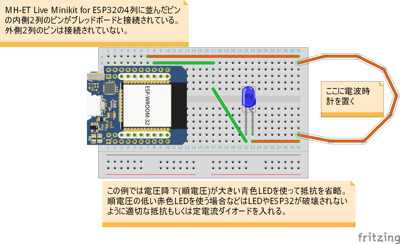
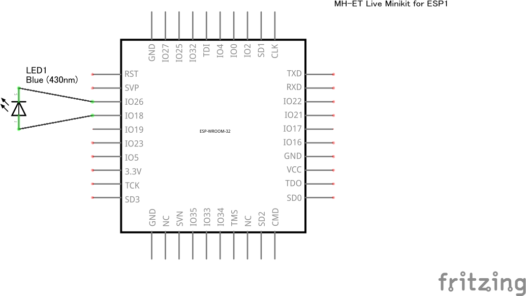
LEDC で40kHz(もしくは60kHz)の信号をESP32のIO18に常時発生しておき、これをLEDのアノード(プラス極)に接続する、標準電波(電波時計)のタイムコードの制御はESP32のIO26をlowにするかハイインピーダンスにするかで制御し、LEDのカソード(マイナス極)に接続する。
上記のIOポート番号の割り当てはもちろん変更可能である。ただし、信号を発生させるピンを変更する際には、LEDCのチャネル変更が必要な場合がある。変更する場合には、後述のプログラムコードJJY.inoのピンの番号、ledcAttachPin および ledcWriteTone の引数になっている CHANNEL を変更する必要がある。
ハードウェア
ブレッドボード図
OLEDシールドは示していないが、使う場合にはMH-ET Live MiniKit for ESP32の上に載せる。
電波時計を置く部分は配線材を巻いて使った方が良いであろう。
回路図
ソフトウェア
Arduinoのスケッチ名を ESP32-NTP-JJY-OLED とする。大きく機能を分けて以下の3つの .inoファイルからスケッチが構成される。
- ESP32-NTP-JJY-OLED.ino
- メイン
- WiFiManagerについては次の記事が参考になる。
- JJY.ino
- 時刻合わせ部
- OLED.ino
- 表示部
- OLEDを接続しない場合でも実行時にエラーは出ない
ESP32-NTP-JJY-OLED.ino
setup と loop の本体。
毎分0秒の際に次の1分のタイムコードが設定されるので、起動した後でも0秒になるまでは不正なタイムコードが出力されている。このため、モニター用LEDの点滅がタイムコードに合致しない場合がある。1分経過すれば(次の0秒を過ぎれば)正しいタイムコードが送出されるはず。
[code]
#if defined(ESP8266)
#include <ESP8266WiFi.h> // https://github.com/esp8266/Arduino
#include <DNSServer.h>
#include <ESP8266WebServer.h>
#include <time.h>
#else
#include <WiFi.h>
#include <DNSServer.h>
#include <WebServer.h>
#endif
#include <WiFiManager.h> // https://github.com/tzapu/WiFiManager
#if defined(TEST)
#define TIMEDIFF 10 /* test */
#else
#define TIMEDIFF 9 /* JST */
#endif
#define JST 3600*TIMEDIFF
extern void setupTone();
extern void checkJJY();
extern void setupOLED();
// WiFiManager
WiFiManager wifiManager;
void setupNTP() {
Serial.begin(115200);
Serial.println();
// setup wifiManager
wifiManager.setConfigPortalTimeout(180);
// autoConnect
wifiManager.autoConnect("NTP-JJY");
// setup NTP
configTime( JST, 0, "ntp.nict.jp", "ntp.jst.mfeed.ad.jp");
}
void setup() {
setupTone();
setupOLED();
setupNTP();
}
void loop() {
checkJJY();
}
[/code]
JJY.ino
タイムコードの出力を行う。
Arduinoで電波時計を合わせよう のコードを利用させていただいた。
[code]
// JJY
// Thid code is based on http://neocat.hatenablog.com/entry/20110328/1301256560
#include <time.h>
#if defined(ESP8266)
extern "C" {
#include "pwm.h"
}
#define TONEPIN D5 // LEDのアノード(+)に接続
#define CONTROLPIN D0 // LEDのカソード(-)に接続
#else
// MH-ET Live
#define TONEPIN 18 // LEDのアノード(+)に接続
#define CONTROLPIN 26 // LEDのカソード(-)に接続
#define CHANNEL 1
void tone(int pin, int hz) {
ledcAttachPin(pin, CHANNEL);
ledcWriteTone(CHANNEL, hz);
}
#endif
// Frequency
int Hz = 40*1000; // 40kHz or 60kHz
byte timecode[60];
// setup Tone
void setupTone() {
tone(TONEPIN, Hz);
}
void signalOn() {
pinMode(CONTROLPIN, OUTPUT); // ピンを出力に設定
digitalWrite(CONTROLPIN, LOW); // Lowに
}
void signalOff() {
digitalWrite(CONTROLPIN, HIGH);
pinMode(CONTROLPIN, INPUT); // ハイインピーダンス状態に
}
int lastsecond = -1;
unsigned long expectedms = -1;
unsigned long startTime;
void checkJJY()
{
struct tm* tm;
time_t n = time(NULL);
tm = localtime(&n);
if ( lastsecond != tm->tm_sec ) {
signalOn();
startTime = millis();
n = time(NULL);
tm = localtime(&n);
lastsecond = tm->tm_sec;
// calc signal duration (ms)
expectedms = calcTimeCodeDuration(tm);
// updateOLED
updateOLED(tm);
}
if ( millis() > startTime + expectedms ) {
signalOff();
expectedms += 1000;
}
}
//=========================== JJY ===========================
#define JJY_MARKER 2
#define JJY_0 8
#define JJY_1 5
#define JJY_VAL(n) ((n)?JJY_1:JJY_0)
unsigned int calcTimeCodeDuration(struct tm* tm)
{
int s = tm->tm_sec;
if (s == 0)
setupTimeCode(tm);
return timecode[s] * 100;
}
void setupTimeCode(struct tm* tm)
{
memset(timecode, JJY_0, sizeof(timecode));
setupTimeCode100(tm->tm_min, timecode);
timecode[0] = JJY_MARKER;
setupTimeCode100(tm->tm_hour, &timecode[10]);
int d = tm->tm_yday + 1;
setupTimeCode100(d/10, &timecode[20]);
setupTimeCode100(d%10*10, &timecode[30]);
int parity1 = 0, parity2 = 0;
int i;
for (i = 12; i < 20; i++) parity1 ^= timecode[i] == JJY_1;
for (i = 1; i < 10; i++) parity2 ^= timecode[i] == JJY_1;
timecode[36] = JJY_VAL(parity1);
timecode[37] = JJY_VAL(parity2);
timecode[40] = JJY_0;
int y = tm->tm_year % 100;
setupTimeCode10(y / 10, &timecode[41]);
setupTimeCode10(y % 10, &timecode[45]);
int w = tm->tm_wday;
setupTimeCode10(w % 10, &timecode[49]);
timecode[49] = JJY_MARKER;
timecode[59] = JJY_MARKER;
/* dump */
for (i = 0; i < 60; i++) {
Serial.print(timecode[i], DEC);
Serial.print(i % 10 == 9 ? "\r\n" : " ");
}
}
void setupTimeCode100(int m, byte code[])
{
int quotient = m / 10;
int remainder = m % 10;
setupTimeCode10(quotient, code);
code[4] = JJY_0;
setupTimeCode10(remainder, &code[5]);
code[9] = JJY_MARKER;
}
void setupTimeCode10(int n, byte code[]) {
for ( int i=3 ; i >= 0 ; i– ) {
code[i] = JJY_VAL(n & 1);
n >>= 1;
}
}
[/code]
OLED.ino
OLEDに時刻の表示を行う。
SFE_MicroOLED ライブラリ付属のサンプル MicroOLED_Clock に基づいている。
[code]
// for WeMos D1 mini OLED Shield https://wiki.wemos.cc/products:d1_mini_shields:oled_shield
// This code is based on MicroOLED_Clock.ino
/****************************************************************
* MicroOLED_Clock.ino
* Analog Clock demo using SFE_MicroOLED Library
* Jim Lindblom @ SparkFun Electronics
* Original Creation Date: October 27, 2014
*
* This sketch uses the MicroOLED library to draw a 3-D projected
* cube, and rotate it along all three axes.
*
* Development environment specifics:
* Arduino 1.0.5
* Arduino Pro 3.3V
* Micro OLED Breakout v1.0
*
* This code is beerware; if you see me (or any other SparkFun employee) at the
* local, and you've found our code helpful, please buy us a round!
*
* Distributed as-is; no warranty is given.
***************************************************************/
// OLED
#include <Wire.h> // Include Wire if you're using I2C
#include <SFE_MicroOLED.h> // Include the SFE_MicroOLED library
#define min(a,b) ((a)>(b)?(b):(a))
//////////////////////////
// MicroOLED Definition //
//////////////////////////
#define PIN_RESET 255 //
#define DC_JUMPER 0 // I2C Addres: 0 – 0x3C, 1 – 0x3D
//////////////////////////////////
// MicroOLED Object Declaration //
//////////////////////////////////
MicroOLED oled(PIN_RESET, DC_JUMPER); // I2C Example
// Use these variables to set the initial time
int hours = 11;
int minutes = 50;
int seconds = 30;
// How fast do you want the clock to spin? Set this to 1 for fun.
// Set this to 1000 to get _about_ 1 second timing.
const int CLOCK_SPEED = 1000;
// Global variables to help draw the clock face:
const int MIDDLE_Y = oled.getLCDHeight() / 2;
const int MIDDLE_X = oled.getLCDWidth() / 2;
int CLOCK_RADIUS;
int POS_12_X, POS_12_Y;
int POS_3_X, POS_3_Y;
int POS_6_X, POS_6_Y;
int POS_9_X, POS_9_Y;
int S_LENGTH;
int M_LENGTH;
int H_LENGTH;
int POS_H_X, POS_H_Y;
int POS_M1_X, POS_M1_Y;
int POS_M0_X, POS_M0_Y;
int POS_S1_X, POS_S1_Y;
int POS_S0_X, POS_S0_Y;
unsigned long lastDraw = 0;
void initClockVariables()
{
// Calculate constants for clock face component positions:
oled.setFontType(0);
CLOCK_RADIUS = min(MIDDLE_X, MIDDLE_Y) – 1;
POS_12_X = MIDDLE_X – oled.getFontWidth();
POS_12_Y = MIDDLE_Y – CLOCK_RADIUS + 2;
POS_3_X = MIDDLE_X + CLOCK_RADIUS – oled.getFontWidth() – 1;
POS_3_Y = MIDDLE_Y – oled.getFontHeight()/2;
POS_6_X = MIDDLE_X – oled.getFontWidth()/2;
POS_6_Y = MIDDLE_Y + CLOCK_RADIUS – oled.getFontHeight() – 1;
POS_9_X = MIDDLE_X – CLOCK_RADIUS + oled.getFontWidth() – 2;
POS_9_Y = MIDDLE_Y – oled.getFontHeight()/2;
// Calculate clock arm lengths
S_LENGTH = CLOCK_RADIUS – 2;
M_LENGTH = S_LENGTH * 0.7;
H_LENGTH = S_LENGTH * 0.5;
// Calculate constants for digital digit positions:
oled.setFontType(0);
// left(x), top(y)
POS_H_X = 0+1;
POS_H_Y = 0+1;
// right(x), top(y)
POS_M1_X = oled.getLCDWidth() – 2*oled.getFontWidth() -1;
POS_M1_Y = 0+1;
POS_M0_X = oled.getLCDWidth() – 1*oled.getFontWidth() -1;
POS_M0_Y = 0+1;
// right(x), bottom(y)
POS_S1_X = oled.getLCDWidth() – 2*oled.getFontWidth() -1;
POS_S1_Y = oled.getLCDHeight()- oled.getFontHeight() -1;
POS_S0_X = oled.getLCDWidth() – 1*oled.getFontWidth() -1;
POS_S0_Y = oled.getLCDHeight()- oled.getFontHeight() -1;
}
void setupOLED()
{
oled.begin(); // Initialize the OLED
oled.clear(PAGE); // Clear the display's internal memory
oled.clear(ALL); // Clear the library's display buffer
oled.display(); // Display what's in the buffer (splashscreen)
initClockVariables();
oled.clear(ALL);
drawFace();
drawArms(hours, minutes, seconds);
oled.display(); // display the memory buffer drawn
}
void updateOLED(struct tm* tm)
{
hours = tm->tm_hour;
minutes = tm->tm_min;
seconds = tm->tm_sec;
// Draw the clock:
oled.clear(PAGE); // Clear the buffer
drawFace(); // Draw the face to the buffer
drawArms(hours, minutes, seconds); // Draw arms to the buffer
drawTime(hours, minutes, seconds); // draw digital time
oled.display(); // Draw the memory buffer
}
// Simple function to increment seconds and then increment minutes
// and hours if necessary.
void updateTime()
{
seconds++; // Increment seconds
if (seconds >= 60) // If seconds overflows (>=60)
{
seconds = 0; // Set seconds back to 0
minutes++; // Increment minutes
if (minutes >= 60) // If minutes overflows (>=60)
{
minutes = 0; // Set minutes back to 0
hours++; // Increment hours
if (hours >= 12) // If hours overflows (>=12)
{
hours = 0; // Set hours back to 0
}
}
}
}
// Draw the clock's three arms: seconds, minutes, hours.
void drawArms(int h, int m, int s)
{
double midHours; // this will be used to slightly adjust the hour hand
static int hx, hy, mx, my, sx, sy;
// Adjust time to shift display 90 degrees ccw
// this will turn the clock the same direction as text:
h -= 3;
m -= 15;
s -= 15;
if (h <= 0)
h += 12;
if (m < 0)
m += 60;
if (s < 0)
s += 60;
// Calculate and draw new lines:
s = map(s, 0, 60, 0, 360); // map the 0-60, to "360 degrees"
sx = S_LENGTH * cos(PI * ((float)s) / 180); // woo trig!
sy = S_LENGTH * sin(PI * ((float)s) / 180); // woo trig!
// draw the second hand:
oled.line(MIDDLE_X, MIDDLE_Y, MIDDLE_X + sx, MIDDLE_Y + sy);
m = map(m, 0, 60, 0, 360); // map the 0-60, to "360 degrees"
mx = M_LENGTH * cos(PI * ((float)m) / 180); // woo trig!
my = M_LENGTH * sin(PI * ((float)m) / 180); // woo trig!
// draw the minute hand
oled.line(MIDDLE_X, MIDDLE_Y, MIDDLE_X + mx, MIDDLE_Y + my);
midHours = minutes/12; // midHours is used to set the hours hand to middling levels between whole hours
h *= 5; // Get hours and midhours to the same scale
h += midHours; // add hours and midhours
h = map(h, 0, 60, 0, 360); // map the 0-60, to "360 degrees"
hx = H_LENGTH * cos(PI * ((float)h) / 180); // woo trig!
hy = H_LENGTH * sin(PI * ((float)h) / 180); // woo trig!
// draw the hour hand:
oled.line(MIDDLE_X, MIDDLE_Y, MIDDLE_X + hx, MIDDLE_Y + hy);
}
// Draw an analog clock face
void drawFace()
{
// Draw the clock border
oled.circle(MIDDLE_X, MIDDLE_Y, CLOCK_RADIUS);
// Draw the clock numbers
oled.setFontType(0); // set font type 0, please see declaration in SFE_MicroOLED.cpp
oled.setCursor(POS_12_X, POS_12_Y); // points cursor to x=27 y=0
oled.print(12);
oled.setCursor(POS_6_X, POS_6_Y);
oled.print(6);
oled.setCursor(POS_9_X, POS_9_Y);
oled.print(9);
oled.setCursor(POS_3_X, POS_3_Y);
oled.print(3);
}
void drawTime(int h, int m, int s)
{
// Draw time numbers
oled.setFontType(0); // set font type 0, please see declaration in SFE_MicroOLED.cpp
oled.setCursor(POS_H_X, POS_H_Y); // points cursor to x=27 y=0
oled.print(h);
oled.setCursor(POS_M1_X, POS_M1_Y);
oled.print(m/10);
oled.setCursor(POS_M0_X, POS_M0_Y);
oled.print(m%10);
oled.setCursor(POS_S1_X, POS_S1_Y);
oled.print(s/10);
oled.setCursor(POS_S0_X, POS_S0_Y);
oled.print(s%10);
}
[/code]
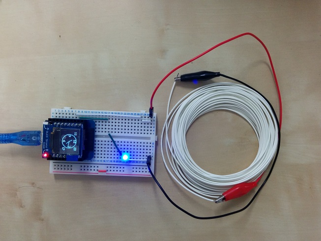
実際の動作風景
ブレッドボード
Fritzingのブレッドボード図とは細部で異なる部分がある。
たとえば、LEDは3mmのものを使っている(Firitzingの図を修正すべきだろう)。
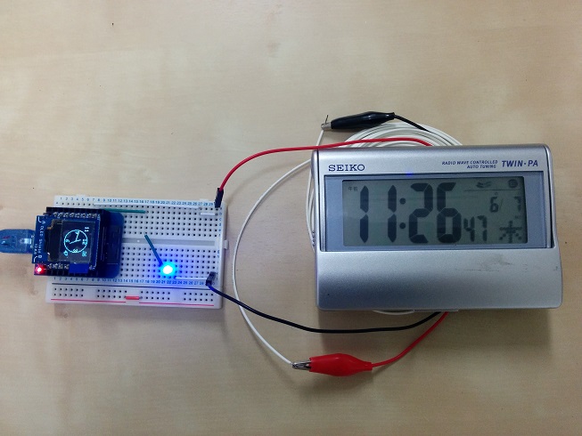
電波時計を置いてみた
電波時計によって置き方やケーブルなどをどのようにするかは工夫が必要。
工夫をすることでだいたいの電波時計の時刻合わせができた。写真の電波時計は感度が悪いようで、屋内ではうまく電波で時刻合わせができていなかったが、今回の実験では時刻合わせができた。
ただし、手元にあるもので試した範囲でもうまく時刻合わせできなかった電波時計が1台あった(古いSEIKOの電波時計 NA501W)。もっとも、うまく時刻合わせできなかった電波時計は窓近くにおいてもこれまで一度も電波で時刻合わせできたことがないこともあり、どのようにすれば時刻を電波で合わせられるのかよく分からない。
WiFiManagerが記憶したIPアドレスのクリア
ESP32 WiFiのSSID、パスワードを外部から設定しアクセスポイントに接続 に記載されているようにWiFiManagerが記憶したIPアドレスのクリアには WifiManager の resetSettings() を呼び出すだけではうまくいかない。(また、IPアドレスを設定した場合もリセットしないと接続がうまく行われないようである。)
Using autoconnect to connect to WIFI, then startConfigPortal, fails to connect/save new credentials に記載されている通り、以下が必要のようである。また、その直後にリセットしないと反映されないようだ。
[code]
WiFi.persistent(true);
WiFi.disconnect(true);
WiFi.persistent(false);
[/code]
上記を利用したIPアドレスクリアのスケッチは以下の通り。
ESP32ClearSavedWiFiIPAddress
WiFiManagerが記憶したIPアドレスをクリアするスケッチである。WiFiManagerが記憶したIPアドレスがある場合には、クリアしてESP.restart()で再起動する。
WiFiManagerが接続可能なIPアドレスを記憶していない場合には、wifiManager.autoConnect()で、AutoConnectAPというSSIDでスマホなどからの接続待ちとなる。記憶しているIPアドレスがあり、このスケッチを実行した場合には、前述の通りESP.restart()で再起動するので、ここに書いたような接続待ちになる。
IPアドレスのクリアの話ではなくなるが、AutoConnectAPに接続後 Web ブラウザからESP32に接続させたいアクセスポイントのSSIDとパスワードを記憶させることができ、その後はその記憶された情報で接続が行われるようになる。
[code]
#include <FS.h> //this needs to be first, or it all crashes and burns…
#if defined(ESP8266)
#include <ESP8266WiFi.h> //https://github.com/esp8266/Arduino
#else
#include <WiFi.h>
#endif
//needed for library
#include <DNSServer.h>
#if defined(ESP8266)
#include <.h>
#elseESP8266WebServer
#include <WebServer.h>
#endif
#include <WiFiManager.h> //https://github.com/tzapu/WiFiManager
void setup() {
// put your setup code here, to run once:
Serial.begin(115200);
Serial.println();
//WiFiManager
//Local intialization. Once its business is done, there is no need to keep it around
WiFiManager wifiManager;
//exit after config instead of connecting
wifiManager.setBreakAfterConfig(true);
//tries to connect to last known settings
//if it does not connect it starts an access point with the specified name
//and goes into a blocking loop awaiting configuration
if (!wifiManager.autoConnect("AutoConnectAP")) {
Serial.println("autoConnect finished");
} else {
//if you get here you have connected to the WiFi
Serial.println("connected…yeey :)");
Serial.print("Local IP: ");
Serial.println(WiFi.localIP());
//reset settings – for testing
wifiManager.resetSettings();
WiFi.persistent(true);
WiFi.disconnect(true);
WiFi.persistent(false);
ESP.restart();
delay(5000);
}
}
void loop() {
// put your main code here, to run repeatedly:
sleep(1000);
Serial.print("!");
}
[/code]