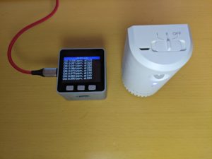
オゾン(O3)脱臭器を使っているが、オゾン臭がしているときは濃度が高すぎないか気になり、オゾン臭がしないときは機能しているのかはっきりしない。
おおよそのオゾンの濃度を調べてみたいと思ったので、測定器やセンサーを少し調べてみた。Aliexpress で3千円台でデジタル出力のセンサーモジュールが買えることがわかったので、それを使って M5Stack で試してみることにした。
目次
オゾンセンサーモジュール ZE27-O3
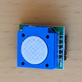
Zhengzhou Winsen Electronics Technology Co., Ltd (炜盛科技)のセンサーモジュール ZE27-O3 を購入した。ヘッダピンを取り付けられるようになっているbreakout board である。
https://www.winsen-sensor.com/sensors/o3-gas-sensor/ze27-o3.html
UART 3V-TTL出力が可能で、ppb 単位の出力が得られる。仕様上は10ppmまで 0.01ppmの分解能ということである。厳密な値が知りたいのではなく、オゾン臭がしている時との大小関係ががわかれば良いので、これで良いとした。
ZE27以外に、ケーブルコネクタがついている ZE25-O3 もあったが、基板の大きさがZE27-O3の方が小さかったので、ZE27-O3を選んだ。しかし、よく仕様をみておらず、ZE27-O3のピンヘッダが2.0mmピッチであることにモジュールが手元に届いてから気がついた。
M5Stackのプロトタイプボードに2.54mm間隔のピンソケットをつけて装着するつもりであったができない。しかたがないので、2.0mmピッチ と 2.54mmピッチ の変換基板を使うことにした。
2.0mmピッチ と 2.54mmピッチ の変換基板は、マルツの「XBeeピッチ変換基板ソケットセット」を流用することにした。ZE27-O3は5ピンしか使わないので、XBeeピッチ変換基板の片側の5ピン分だけを利用した。変換基板は、ZE27-O3にはちょっと大きすぎるが、M5Stackのプロトタイプ基板に載る大きさなのでそのまま使うことにした。
使用した部品等
- M5Stack Gray
- M5Stack Base26 Proto Industrial Board Module
- 2.0mmピッチ と 2.54mmピッチ の変換基板が必要になったこともあり、Base 15では高さが不足して収まらない。
- Base26 にもプロトタイプボードが含まれているのでそれを使えば次の PROTO Boardは不要。
- M5Stack プロトタイプ基板 PROTO Board – DIY Pegboard for Prototyping Development
- XBeeピッチ変換基板ソケットセット
- Ozone Sensor Module ZE27-O3
- 2.0mmピッチ ヘッダピン (ZE27-O3用5本)
組み立て
ピンの対応
| ZE27-O3 | M5Stack-Gray |
| pin 1 – Vin | 5v |
| pin 2 – TXD | GPIO16 – RXD2 |
| pin 3 – RXD | GPIO17 – TXD2 |
| pin 4 – GND | GND |
| pin 5 – NC |
基板
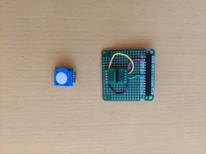
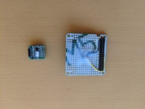
基板の緑面(1枚目)の灰色と黄色の配線は実際には使っていない(つながっていない)。配線できなかったので、基板の白面(2枚目)でGNDと16番pinを接続している。
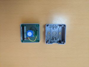
M5Stack Gray と Proto Boardと Base26
動作確認プログラム
https://github.com/fega/winsen-ze03-arduino-library と https://github.com/m5stack/M5Stack/blob/master/examples/Advanced/Display/TFT_Terminal/TFT_Terminal.ino を基にプログラムを作成した。
開発ツールには、PlatformIO IDE for VSCode を利用した。
WinsenZE03Example.ino
|
1 2 3 4 5 6 7 8 9 10 11 12 13 14 15 16 17 18 19 20 21 22 23 24 25 26 27 28 29 30 31 32 33 34 35 36 37 38 39 40 41 42 43 44 45 46 47 48 49 50 51 52 53 54 55 56 57 58 59 60 61 62 63 64 |
/* WinsenZE03.h - This library allows you to set and read the ZE03 Winsen Sensor module. More information: https://github.com/fega/winsen-ze03-arduino-library Created by Fabian Gutierrez <fega.hg@gmail.com>, March 17, 2017. MIT. */ /* This file is based on https://github.com/fega/winsen-ze03-arduino-library modified by epi on 2021/Feb/17 for ozone (O3) sensor ZE27-O3 */ #include <WinsenZE03.h> #include <M5Stack.h> #include <Wire.h> extern void termInit(const char *title); extern void termPutchar(char data); extern void termPrintString(const char *str); WinsenZE03 sensor; #define INTERVAL 5 * 1000 void setup() { bool LCDenable = true, SDEnable = false, SerialEnable = true, I2CEnable = false; M5.begin(LCDenable, SDEnable, SerialEnable, I2CEnable); Serial.begin(115200); termInit("ZE27-O3"); Serial2.begin(9600); sensor.begin(&Serial2, O3); sensor.setAs(QA); } unsigned long lastTime; void loop() { unsigned long now = millis(); if (M5.BtnA.wasPressed() || now > lastTime + INTERVAL) { int startupTime = now / 1000; lastTime = now; float ppm = sensor.readManual(); // O3 value to string char ppmBuf[32]; dtostrf(ppm, 5, 3, ppmBuf); // compose output message char lineBuf[128]; sprintf(lineBuf, "O3: %s ppm, at %d", ppmBuf, startupTime); Serial.printf("%s\n", lineBuf); termPrintString(lineBuf); termPutchar('\r'); } M5.update(); } |
WinsenZE03.h
|
1 2 3 4 5 6 7 8 9 10 11 12 13 14 15 16 17 18 19 20 21 22 23 24 25 26 27 28 29 30 31 32 33 34 35 36 37 38 39 40 41 42 43 44 45 46 |
/* Morse.h - This library allows you to set and read the ZE03 Winsen Sensor module. Created by Fabian Gutierrez, March 12, 20017. MIT. */ /* This file is based on https://github.com/fega/winsen-ze03-arduino-library modified by epi on 2021/Feb/17 for ozone (O3) sensor ZE27-O3 */ #ifndef WinsenZE03_h #define WinsenZE03_h #include "Arduino.h" #define CO 1 #define SO2 2 #define NO2 2 #define O2 2 #define NH3 1 #define H2S 1 #define HF 1 #define CL2 2 #define O3 2 #define QA false #define ACTIVE true class WinsenZE03 { public: WinsenZE03(); void begin(Stream *ser, int type); void setAs(bool active); float readManual(); #if 0 /* epi 2021/Feb/17 */ float readContinuous(); #endif private: void debugPrint(byte arr[]); Stream *_s; //Serial1 - Serial3 are USARTClass objects. int _type; }; #endif |
WinsenZE03.cpp
|
1 2 3 4 5 6 7 8 9 10 11 12 13 14 15 16 17 18 19 20 21 22 23 24 25 26 27 28 29 30 31 32 33 34 35 36 37 38 39 40 41 42 43 44 45 46 47 48 49 50 51 52 53 54 55 56 57 58 59 60 61 62 63 64 65 66 67 68 69 70 71 72 73 74 75 76 77 78 79 80 81 82 83 84 85 86 87 88 89 90 91 92 93 94 95 96 97 98 99 100 101 102 103 104 105 106 107 |
/* WinsenZE03.h - This library allows you to set and read the ZE03 Winsen Sensor module. Created by Fabian Gutierrez, March 12, 2017. MIT. */ /* This file is based on https://github.com/fega/winsen-ze03-arduino-library modified by epi on 2021/Feb/17 for ozone (O3) sensor ZE27-O3 */ #include "Arduino.h" #include "WinsenZE03.h" #define DEVMODE true //Set as true to debug WinsenZE03::WinsenZE03() { _s = NULL; } void WinsenZE03::begin(Stream *ser, int type) { _s = ser; _type = type; } void WinsenZE03::setAs(bool active) { byte setConfig[] = {0xFF, 0x01, 0x78, 0x41, 0x00, 0x00, 0x00, 0x00, 0x46}; //QA config byte response[9] = {0x00, 0x00, 0x00, 0x00, 0x00, 0x00, 0x00, 0x00, 0x00}; if (active) { setConfig[3] = 0x40; setConfig[8] = 0x47; } _s->write(setConfig, sizeof(setConfig)); // Wait for the response delay(2000); //Flush the incomming buffer if (_s->available() > 0) { _s->readBytes(response, 9); } while (_s->available() > 0) { byte c = _s->read(); } } #if 0 /* epi 2021/Feb/17 */ float WinsenZE03::readContinuous() { if (_s->available() > 0) { byte measure[8]; _s->readBytes(measure, 9); float ppm = 0.001 * (measure[4] * 256 + measure[5]); return ppm; } } #endif float WinsenZE03::readManual() { float ppm; byte petition[] = {0xFF, 0x01, 0x86, 0x00, 0x00, 0x00, 0x00, 0x00, 0x79}; // Petition to get a single result byte measure[8] = {0x00, 0x00, 0x00, 0x00, 0x00, 0x00, 0x00, 0x00}; // Space for the response _s->write(petition, sizeof(petition)); delay(1500); // read if (_s->available() > 0) { _s->readBytes(measure, 9); } // calculate if (measure[0] == 0xff && measure[1] == 0x86) { ppm = 0.001 * (measure[2] * 256 + measure[3]); // this formula depends of the sensor is in the dataSheet } else { ppm = -1; } return ppm; } void WinsenZE03::debugPrint(byte arr[]) { Serial.print(arr[0], HEX); Serial.print(" "); Serial.print(arr[1], HEX); Serial.print(" "); Serial.print(arr[2], HEX); Serial.print(" "); Serial.print(arr[3], HEX); Serial.print(" "); Serial.print(arr[4], HEX); Serial.print(" "); Serial.print(arr[5], HEX); Serial.print(" "); Serial.print(arr[6], HEX); Serial.print(" "); Serial.print(arr[7], HEX); Serial.print(" "); Serial.println(arr[8], HEX); } |
TFT_Terminal.cpp
|
1 2 3 4 5 6 7 8 9 10 11 12 13 14 15 16 17 18 19 20 21 22 23 24 25 26 27 28 29 30 31 32 33 34 35 36 37 38 39 40 41 42 43 44 45 46 47 48 49 50 51 52 53 54 55 56 57 58 59 60 61 62 63 64 65 66 67 68 69 70 71 72 73 74 75 76 77 78 79 80 81 82 83 84 85 86 87 88 89 90 91 92 93 94 95 96 97 98 99 100 101 102 103 104 105 106 107 108 109 110 111 112 113 114 115 116 117 118 119 120 121 122 123 124 125 126 127 128 129 130 131 132 133 134 135 136 137 138 139 140 141 142 143 144 145 146 147 148 149 150 151 152 153 154 155 156 157 158 159 160 |
/************************************************************* This sketch implements a simple serial receive terminal program for monitoring serial debug messages from another board. Connect GND to target board GND Connect RX line to TX line of target board Make sure the target and terminal have the same baud rate and serial stettings! The sketch works with the ILI9341 TFT 240x320 display and the called up libraries. The sketch uses the hardware scrolling feature of the display. Modification of this sketch may lead to problems unless the ILI9341 data sheet has been understood! Updated by Bodmer 21/12/16 for TFT_eSPI library: https://github.com/Bodmer/TFT_eSPI BSD license applies, all text above must be included in any redistribution *************************************************************/ /* This file is based on https://github.com/m5stack/M5Stack/blob/master/examples/Advanced/Display/TFT_Terminal/TFT_Terminal.ino This file is modified by epi */ #include <M5Stack.h> // The scrolling area must be a integral multiple of TEXT_HEIGHT #define TEXT_HEIGHT 24 // Height of text to be printed and scrolled #define TOP_FIXED_AREA 24 // Number of lines in top fixed area (lines counted from top of screen) #define BOT_FIXED_AREA 0 // Number of lines in bottom fixed area (lines counted from bottom of screen) #define YMAX 240 // Bottom of screen area #define XMAX 320 // The initial y coordinate of the top of the scrolling area uint16_t yStart = TOP_FIXED_AREA; // yArea must be a integral multiple of TEXT_HEIGHT uint16_t yArea = YMAX - TOP_FIXED_AREA - BOT_FIXED_AREA; // The initial y coordinate of the top of the bottom text line uint16_t yDraw = YMAX - BOT_FIXED_AREA - TEXT_HEIGHT; //uint16_t yDraw = 0; // Keep track of the drawing x coordinate uint16_t xPos = 0; // For the byte we read from the serial port byte data = 0; // A few test variables used during debugging boolean change_colour = 1; boolean selected = 1; // font type // 1: 8 pixel ASCII // 2: 16 pixel ASCII // 4: 24 pixel ASCII uint16_t fontType = 4; // We have to blank the top line each time the display is scrolled, but this takes up to 13 milliseconds // for a full width line, meanwhile the serial buffer may be filling... and overflowing // We can speed up scrolling of short text lines by just blanking the character we drew //int blank[19]; // We keep all the strings pixel lengths to optimise the speed of the top line blanking // ############################################################################################## // Setup the vertical scrolling start address pointer // ############################################################################################## void scrollAddress(uint16_t vsp) { M5.Lcd.writecommand(ILI9341_VSCRSADD); // Vertical scrolling pointer M5.Lcd.writedata(vsp >> 8); M5.Lcd.writedata(vsp); } // ############################################################################################## // Call this function to scroll the display one text line // ############################################################################################## int scroll_line() { int yTemp = yStart; // Store the old yStart, this is where we draw the next line // Use the record of line lengths to optimise the rectangle size we need to erase the top line // M5.Lcd.fillRect(0,yStart,blank[(yStart-TOP_FIXED_AREA)/TEXT_HEIGHT],TEXT_HEIGHT, TFT_BLACK); M5.Lcd.fillRect(0, yStart, XMAX, TEXT_HEIGHT, TFT_BLACK); // Change the top of the scroll area yStart += TEXT_HEIGHT; // The value must wrap around as the screen memory is a circular buffer if (yStart >= YMAX - BOT_FIXED_AREA) yStart = TOP_FIXED_AREA + (yStart - YMAX + BOT_FIXED_AREA); //if (yStart >= YMAX) yStart = 0; // Now we can scroll the display scrollAddress(yStart); return yTemp; } // ############################################################################################## // Setup a portion of the screen for vertical scrolling // ############################################################################################## // We are using a hardware feature of the display, so we can only scroll in portrait orientation void setupScrollArea(uint16_t tfa, uint16_t bfa) { M5.Lcd.writecommand(ILI9341_VSCRDEF); // Vertical scroll definition M5.Lcd.writedata(tfa >> 8); // Top Fixed Area line count M5.Lcd.writedata(tfa); M5.Lcd.writedata((YMAX - tfa - bfa) >> 8); // Vertical Scrolling Area line count M5.Lcd.writedata(YMAX - tfa - bfa); M5.Lcd.writedata(bfa >> 8); // Bottom Fixed Area line count M5.Lcd.writedata(bfa); } void termPutchar(char data) { // while (Serial.available()) { // data = Serial.read(); // If it is a CR or we are near end of line then scroll one line if (data == '\r' || xPos > 311) { xPos = 0; yDraw = scroll_line(); // It can take 13ms to scroll and blank 16 pixel lines } if (data > 31 && data < 128) { xPos += M5.Lcd.drawChar(data, xPos, yDraw, fontType); //blank[(18+(yStart-TOP_FIXED_AREA)/textHeight)%19]=xPos; // Keep a record of line lengths } //change_colour = 1; // Line to indicate buffer is being emptied } } void termPrintString(const char *str) { while (*str) termPutchar(*str++); } void termInit(const char *title) { // Setup the TFT display // M5.Lcd.setRotation(5); // Must be setRotation(0) for this sketch to work correctly M5.Lcd.fillScreen(TFT_BLACK); M5.Lcd.setTextColor(TFT_WHITE, TFT_BLUE); M5.Lcd.fillRect(0, 0, XMAX, TEXT_HEIGHT, TFT_BLUE); M5.Lcd.drawCentreString(title, XMAX / 2, 0, fontType); // Change colour for scrolling zone text M5.Lcd.setTextColor(TFT_WHITE, TFT_BLACK); // Setup scroll area setupScrollArea(TOP_FIXED_AREA, BOT_FIXED_AREA); //setupScrollArea(0, 0); // Zero the array //for (byte i = 0; i<18; i++) blank[i]=0; } |
platformio.ini
|
1 2 3 4 5 6 7 8 9 10 11 12 13 14 15 16 17 18 |
; PlatformIO Project Configuration File ; ; Build options: build flags, source filter ; Upload options: custom upload port, speed and extra flags ; Library options: dependencies, extra library storages ; Advanced options: extra scripting ; ; Please visit documentation for the other options and examples ; https://docs.platformio.org/page/projectconf.html [env:m5stack] platform = espressif32 board = m5stack-grey framework = arduino ; Serial Monitor options monitor_speed = 115200 |
動作状況
起動したばかりの時を除いて最小値は、0.020ppmのようだ。これより小さい値は出力されない。0.001ppmの桁まで変化する。
アマゾンで3千円台で購入した手元の小型のオゾン脱臭器を動作させて、脱臭器のすぐ近くにセンサーを置くと測定値は、0.1ppm を超えたが、0.5ppmを超えることはなかった。1mくらい離れたところにセンサーを置くとオゾン脱臭器動作中は0.05ppm以下。脱臭器を止めてしばらく経てば、0.020ppm になった。オゾン臭を感じられない場合でも、センサーで脱臭器が動作していることは確認できた。
一方、オゾン脱臭器を動作させておらず、臭気を感じない場合でも、0.035ppmくらいになることがある。しかし、これがセンサーの誤差によるものなのか、センサーに影響する NO2やCl2などのガスのせいなのか、イオンを発生させる機能がついているエアコンからO3も少し出ているのせいなのか、それとも他の原因があるのかははっきりしなかった。
